
Overview
Load-locks are small anti-chambers used for the insertion of substrates and substrate masks. Load-locks are primarily designed to reduce the pump down time of your deposition system, hence increases the number of deposition runs per time unit. Because of the low volume of the load-lock and a proper pumping set, the pump down time is very quick (around 5×10⁻⁶ mbar in 10 minutes) compared to that of a large deposition chamber.
However, there are many more advantages of having a load-lock connected to your deposition chamber. With a load-lock, the deposition chamber is only vented for routinely maintenance, such as, cleaning or refilling of the sources. This also makes the base pressure of the system better than for a cycled system, which results in higher quality films as the Oxygen partial pressure is lower.
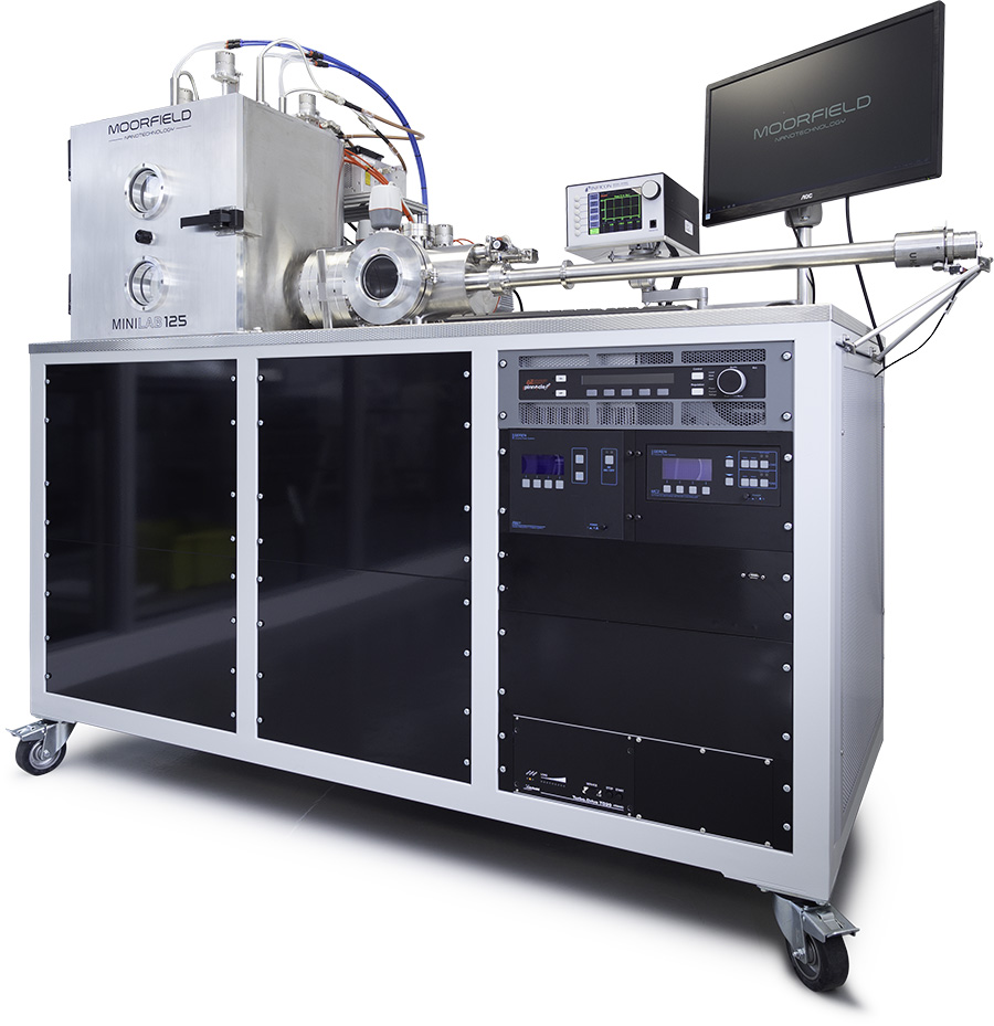
Figure 1: Moorfield Minilab125 deposition system with a linear load-lock
There are also possibilities to add pre or post deposition functionalities into the load-lock. With these functionalities there will be an increase in the film quality. An example for such a functionality is an etching stage. With the etching stage you can eliminate possible oxidation of the substrate by removing the contaminants before the deposition process is started. Another advantage of having a etch stage in the load-lock and not in the deposition chamber is, that the contaminations are contained in the load-lock and thus there will be no thermal migration of these contaminations during the deposition run.
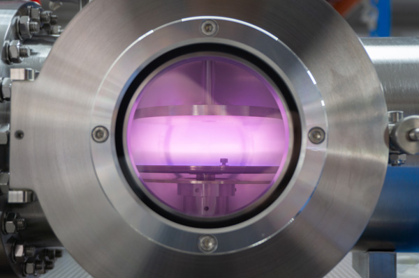
Figure 2: Reactive ion etch stage inside a load-lock
End station linear load-locks
Linear load-locks are the most common sort of load-locks. The load-lock has a single axis transfer along the length of the load-lock chamber. The Turbomolecular pump is positioned horizontally and faces the entry door. A gate valve, which can be manual or pneumatic, separates the load-lock from the process chamber.
Figure 3: Example of an end station linear load-lock fitted to a Moorfield Minilab060
the platen were the substrate sits on is carried by a magnetically coupled linear transport arm into the process chamber. In the process chamber the substrate stage is accommodated to received the platen and takes it to the correct position before starting the deposition run, via a vertical Z-shift (manual or motorized). All the Moorfield integrated load-locks are fitted with a semi-automated transfer and safety interlocks for pressure, gate valve and probe arm positioning.
Mid station linear load-locks
Mid station load-locks are designed to be shared between two in-line systems. These load-locks are ideal to use in device manufacturing, where you want to use different deposition techniques in one run, without breaking the vacuum. In the mid station linear load-locks, the turbomolecular pump is positioned vertically from below and the entry door is positioned vertically about the central position.
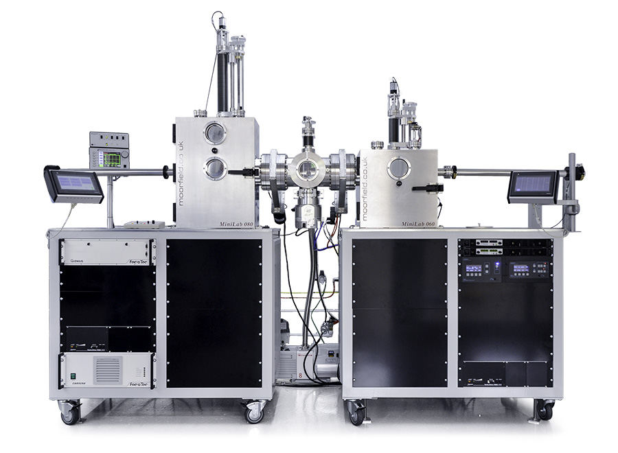
Figure 4: A Moorfield Minilab080 and a Minilab060 connected via a mid station linear load-lock
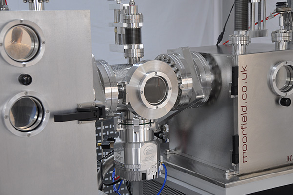
Figure 5: Close view of a mid station linear load-lock, with the turbomolecular pump below the load-lock
Right angle transfer load-locks
Right angle transefer load-locks are designed to be shared between two ssytems. This load-lock has a dual axis transfer along the length and the widht of the loac-lock chamber. In the right angle transfer load-locks the turbomolecular pump is positioned vertically below the chamber and facing the entry door, which is positioned on top of the load-lock chamber. Gate valves (manual or pneumatic) are used to separates the load-lock from the process chamber.
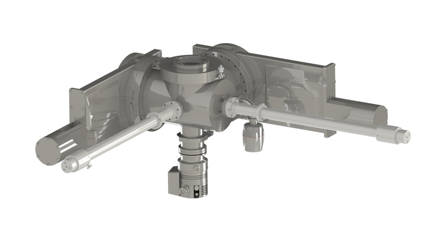
Figure 6: A right angle transfer load lock design
Options for load-lock systems
Parking stage
Parking stations are designed to allow a substrate platen to be parked inside the load-lock prior to deposition
Annealing station
Annealing stations are designed for pre and post heating of the substrate in controlled atmosphere. Various temperatures and gas admission options can be fitted.
RIE station
RF-plasma etch stages are designed to etch substrates prior to the deposition process. The RF-plasma etch stage gives you the possibility to etch in standard form (1W/cm2) or to use “soft etching” for 2D materials in high resolution RF-form. Different gas packages and pressure control options can be fitted.
Z-shift
In-situ Z-shift (manual or mortised) is required on some load-lock modules, such as automatic mask exchange.
Parking cassette and elevator
The parking cassette and elevator allows for the stacking of multiple substrate platens or shadow masks. This allows for automatic substrate/mask exchange, without breaking the vacuum.
Substrate platens
Substrate platens with different sizes can be fitted in the load-lock, ranging from 2” to 8”. Substrate platens can be made of different materials, for instance, SS304, SS316, Ceramic, graphite or molybdenum.
Gas introduction sub-systems
Gas Introduction sub-systems are designed to introduce gas into the load-lock. Up to 4 Mass flow controllers can be fitted. Turbo throttle valves and capacitance manometers options can be fitted.
Gas cooling station
Gas cooling stations are designed to allow in-situ platen temperature to be monitored whilst gas is injected directly below the platen.
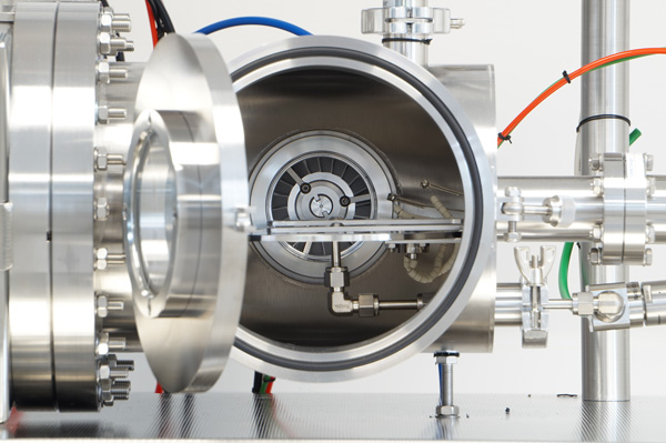
Figure 7: Gas cooling station inside the load-lock
All the Moorfield load-locks are fitted with gate valves, wide range gauges (from atmosphere to 10-8 mbar), and dedicated pumping systems (Turbomolecular pump and backing pump).
Key Benefits of load-lock systems
- Increase tool productivity
- Reduces process chamber vent cycles
- Reduces process turbomolecular pump wear
- Increases film quality
- Allows for offline processes (Anneal, etch)
- Single or multiple substrate pass options
Applications
- Fundamental research
- Education
- Product R&D
- Pilot-scale production