DC and AC characterization of a Vanadium Redox Flow Battery (VRFB) using a Pinflow 20 cm² test lab cell
Redox Flow Batteries (RFBs) stand out from all electrochemical energy storage systems as a highly attractive candidate for the following reasons:
Among the various technologies that are available, vanadium redox couples (VV and V IV for the positive electrode, VII and VIII for the negative electrode) present a remarkable durability mainly due to: i) the absence of mutual contamination of electrolytes (as both electrolytes on the positive and negative side of the cell contain vanadium), ii) the absence of volume changes of the electrodes related to metal plating or ion insertion (both electrolytes react at inert electrodes and remain liquid) [2]
In this application note, a Vanadium Redox Flow Battery (VRFB) was characterized using typical DC and AC techniques: galvanostatic charge and discharge cycling and Electrochemical Impedance Spectroscopy (EIS)
Figure 1 shows the schematic of a Redox Flow Battery. As is the case in any electrochemical device system, the RFB converts electrochemical energy into electricity. Unlike conventional batteries, like Li-ion or Ni-Cd batteries, which are closed systems, where the storage and conversion of energy take place in the same place, RFBs, like fuel cells, are open systems where energy conversion and storage are separated. The electrochemical energy is stored in the electrolytes, in the form of a redox Nernst potential difference between both electrolytes.

In the case of a VRFB, the electrolyte on the positive side of the cell (“catholyte” 1 ) contains the redox couple VO2 + /VO 2+ with a standard potential of 1.000 V/NHE; the electrolyte on the negative side of the cell (“anolyte” 2 ) contains the redox couple V 3+/V 2+ with a standard potential of -0.255 V/NHE.
The following reactions take place at the positive inert3 electrode
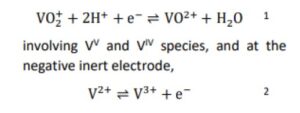
During discharge:
Please click on ‘Request Application Note’ and we will send you the full application note ‘DC and AC characterization of a Vanadium Redox Flow Battery (VRFB) using a Pinflow 20 cm² test lab cell’.