Scratch Testing Analysis of Thermal Spray Coatings

Introduction
Thermal spraying is a specific coating technique in which melted material is projected onto a surface to coat it. Compared to other deposition techniques, the thermal sprays offer the ability to cover large area at high deposition rates and provide thicker coatings. Thermal sprays are used in various industries such as aerospace, automobile, marine and heavy machinery. The applications for those coatings cover wear and abrasion resistance, low friction, corrosion protection, altering thermal and electrical conductivity and many others.
Testing Problematic
The projection of melted material onto the substrate surface forms a highly inhomogeneous coating consisting of a multitude of “pancake-like” splats called lamellae formed by the flattening of the material droplet.
The size of those lamellae along with the varying degrees of porosity are typically used to characterize the thermal spray coatings. But this deposition technique results in a unique microstructure that presents properties significantly different than bulk materials.
The different types of thermal spraying processes (flame, arc, plasma, high velocity oxy fuel and detonation gun spraying ) also increase the complexity of the material problematic by yielding different structures.
The durability and functionality of these coatings is highly dependent on the cohesion strength of the resulting coating but also on its adhesion to the substrate. It is therefore necessary to test those coating in their “as deposited” state to investigate the effects of deposition techniques, spraying parameters such as velocities, and substrate surface preparation.
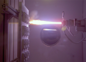
Figure 1: Thermal Spray deposition (Vacuum Plasma Spraying) 1
Test Methodolgy
The substrate / thermal spray system is mounted as a cross section in a metallographic mount and polished to expose the interface between the substrate and coating. A constant load scratch is generated by dragging a sphero-conical diamond tip perpendicular to the interface and moving from the substrate towards the coating (Figure 2). The scratch is set up to finish in the mounting material.
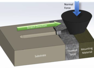
Figure 2: Cross section scratch testing principle
Two main types of failures can be created as shown in Figure 3:
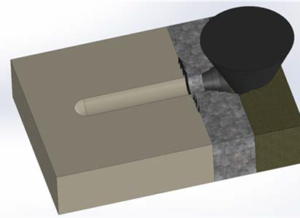
The normal force on the tip is adjusted to create either failure at the free surface of the thermal spray or at the interface between the substrate and the thermal spray coating.
Please click on ‘Request Application Note’ and we will send you the full application note: ‘Scratch Testing Analysis of Thermal Spray Coatings’.